Look and Learn: Towards Cheap, Flexible Robots
S.E. Hodges and R..J. Richards,
Cambridge University Engineering Department,
Mill Lane, Cambridge, CB2 1RX, U.K. seh,rjrQeng.cam.ac.uk
Abstract Robots are currently used in many industrial applications since they offer numerous advantages over simpler forms of mechanisation and human labour. However, their use is by no means as widespread as was envisaged when industrial robots first became available.
This paper highlights the problems which have limited the use of industrial robotic automation. To alleviate many of these, including the prohibitive cost of many robot solutions, an approach based on the use of a computer vision system and a learning controller is outlined. Advances in hardware and software technology in recent years which have made this possible are described.
The potential of the proposed approach is demonstrated using a cheaply constructed robot mechanism and computer vision system which is able to drill printed circuit boards (PCBs). The techniques used for successful implementation are presented, along with improvements which could be made.
[1] PROBLEMS IN INDUSTRIAL ROBOTICS
The advantages of robots over simpler forms of mechanisation and human labour are well documented (see [1] for example). They include higher productivity, reduced labour costs, reduced downtime, increased quality and consistency, and inventory and scrap savings. In addition, the same robot can potentially be used for a variety of tasks. However, the single most prohibitive aspect of using robotic automation is the initial investment required in purchasing the robot itself. The high mechanical specifications required to repetitively perform the given task with consistent accuracy result in an expensive machine. Implementing a robotic system also incurs costs in addition to the basic price of the robot. These include the design, construction and installation of specialised tooling such as parts positioners and fixturing, and operating expenses such as labour and maintenance costs [1]. In order to justify the high capital equipment and running costs involved in robotics, high machine utilisation is a prerequisite.
Robotic systems are designed to be versatile to accommodate changes in the production line. However, any significant change in the product will involve reprogramming the controller and replacing fixturing in the work cell and the end-effectors. This can be expensive and time consuming.
A further problem is the inconsistency in parts which is inevitably present. The typical solution to this problem is to increase the quality control of the previous process to reduce any variation [2], which is again costly.
If robots were cheaper to purchase and operate, many- more industrial processes would become suitable for automation. High machine utilisation, along with correspondingly high product volumes, would no longer be prerequisite. If the robot was more flexible, then it would be able to cope with variations in the product and its position, again reducing expense. This would increase the application base of robotics to include small batch, high variability environments.
2 LOOK AND LEARN: A NEW APPROACH TO ROBOTICS 2.1 Looking for a better solution
Robotic vision systems are not uncommon in industry, but they are generally very limited. Typically, a video camera will be used to take a single image of a part, so that any variations in its position and shape can be compensated for. Traditionally, such systems are expensive to buy and install.
If a vision system is used to monitor the position of the robot end-effector as well as the target position, it is possible to calculate the error in the end-effector position in image coordinates. This information can be used by the controller to achieve accurate positioning. The idea of visual servoing is not new - many researchers have tried similar schemes [3, 4]. However, rather than implementing visual servoing on a standard industrial robot, which is intrinsically capable of a high positional accuracy and repeatability, this work uses a very low accuracy, cheaply constructed robot. Backlash, link flexibility and poor joint feedback can all be compensated for by the controller. Due to the cheap construction, the robot will be more affected by component wear, temperature changes, etc. as time passes; the controller will automatically make appropriate compensation. Variation between different robots of a given specification - inevitable if low tolerance components are used in construction - is not critical. In this way, the capital and maintenance costs of a robotic system can be dramatically reduced, without compromising accuracy.
It is possible to mount a camera on the robot arm to provide an image of just the end-effector and part of the workpiece. Since the camera now only looks at the area of interest, a higher resolution is attained at no extra cost.
Another advantage of looking at the workpiece and the end effector and using this information as a basis for feedback is that any variations in the position of the workpiece are automatically compensated for. As long as the visual cues which comprise the target do not change, even variations in the parts themselves should not present a challenge - small batches of different products which require similar processing can be accommodated.
2.2 Learning to improve performance
The main problem with the scheme outlined in the previous section is that the visual feedback loop is very slow compared with traditional joint position feedback. Calculating the positional error from images of the workspace is computationally demanding. Many iterations of the feedback loop may be required to servo to the target, which means that the execution of a complete move can be time consuming. Specialised image processing hardware would reduce the problem, but is expensive and therefore defeats the aim of producing a cheap robot system. A more attractive solution is to reduce the number of iterations required.
If joint position feedback is available, an accurate model of the mechanism would allow the error as seen by the camera to be transformed into an error in joint positions. This scheme is impractical for the proposed low specification robot, because the exact characteristics of the mechanism cannot easily be modelled, and the model will differ from one machine to the next. However, providing the mechanism is repeatable, it is possible to learn the transform between joint positions and the end-effector position as seen by the camera as moves are made. Even the effects of backlash and other non-linearities can be learned, provided they are deterministic. Over time, more experience is gained, and the mapping becomes more complete. In effect, a model of the mechanism is generated by the controller.
Each time the vision system detects a positional error (which will be expressed in image coordinates), the move required to compensate can be estimated using the model learned and executed quickly using joint position feedback. Following each move, visual feedback is still used to check if the target has been reached successfully. However, the number of iterations required should be fewer and hence the execution time for a complete move much less than before.
3 IMPLEMENTATION ISSUES
The ideas discussed in the last two sections do not rely on significant technological advances for successful implementation. The novelty of the system is the integration of a number of existing technologies with the aim of producing a cheap, flexible robot without compromising accuracy or dramatically reducing speed of operation.
3.1 Machine vision
Visual servoing has been studied extensively, as has active vision, the process of mounting the camera on the arm itself. The originality of this approach is the application of these techniques with the central aim of making robotics more cost effective. This is achieved by shifting emphasis from the mechanical robot hardware to a vision and control system, i.e. computer hardware and software. The many ideas in image processing introduced and developed over the last few years mean that the application of vision to industrial robotic tasks has become increasingly feasible. For example, active contours [5] allow edges in the image to be tracked in real-time as the end effector servos to its target; partial summation can dramatically reduce image processing times compared with traditional convolution techniques [6] and projective transformations [7, 8] enable accurate modelling of viewed objects.
3.2 Learning techniques
Many different learning schemes for robot control have been extensively studied. In recent years, particular attention has been given to neural network-based algorithms [9, 10] such as multi-layer perceptrons and self- organising networks. These techniques rely on a model of the transformation which is to be learned; as experience is gained, the model is refined with the aim of making it more accurate.
An alternative approach is memory-based, learning [11]. In this scheme, experiences are stored explicitly in a large look-up table. In this way, similar previous experiences can be found and used to predict the transformation in the current situation. A particular form of memory-based learning which has been shown to be suitable for learning in robot control applications is State-Action-Behaviour (SAB) learning [11]. The essence of this is to encapsulate the state of the system, and then store this along with the control action applied and the behaviour which resulted. This means that at any point in the future, if the system is in a state which was experienced earlier, and that the behaviour required has been previously generated from that state, it can be replicated by applying the same action as before. Methods for efficient storage, retrieval of similar experiences and generalisation to situations not yet experienced have been studied extensively [11, 12].
3.3 Hardware
 |
There have also been significant technological advances in computer hardware in recent years. The power of microprocessors is increasing at around 35% per year whilst cost is falling [13]; real-time image processing is now possible at a modest cost. Computer memory prices are falling in a similar manner whilst capacity increases; thus the requirements of memory-based learning can be met. Related advances in VLSI technology have significantly- brought down the cost and size of charge-coupled device (CCD) cameras. It is now possible to buy a CCD chip which incorporates scanning circuitry and an analogue- to-digital converter, allowing direct interface with a digital computer without the need for a frame grabber [14].
It is reasonable to expect that computer hardware will continue to decrease in cost whilst increasing in performance in the future. Mechanical hardware costs, on the other hand, are likely to continue to stay in line with inflation in future years. Therefore, it seems sensible to make a shift from mechanics to electronic hardware and associated software in robotics applications. In this way, robotic solutions will become increasingly economically viable.
4 EXPERIMENTAL SYSTEM
This work uses printed circuit board drilling as a specific industrial application in order to demonstrate the feasibility of the ideas discussed so far. The use of vision to facilitate robust automation of PCB manufacture has been studied in the past [15, 16], but without particular consideration of system cost.
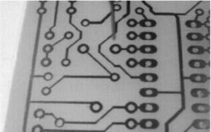 Figure 2: Typical imago of PCB to bo drilled.
|
4.1 Mechanical hardware
Toothed belts, driven by stepper motors, are used to move the PCB in two dimensions via two perpendicular rods (see Figure 1). Friction in the system is high compared with inertia which means that the dynamics of the system can be ignored. Due to the flexibility of the rods and play in the joints, a large amount of backlash is present. A single fixed camera views an area in the centre of the workspace and is used to monitor the end of the drill bit, along with the part of the PCB concerned. Figure
2 shows a typical image. The mechanical costs of the rig, which is designed to be cheap rather than accurate or repeatable, were around 1200. In addition to this, a CCD camera, off-the-shelf frame grabber and 486-based PC are needed to provide the necessary visual feedback, bringing the total system cost to around 11,700.
Since only one camera is used, calibration is necessary to compensate for lack of depth information. For drilling, this means that the height of the drill above the PCB must be known. With this information, it is possible to position the drill bit directly above the hole to be drilled.
4.2 Visual feedback
In order to prove that visual feedback can be used to compensate for the poor mechanics of the system, a simple controller was applied to the task of drilling holes. Proportional feedback was used to iteratively reduce any error in the location of the PCB. In initial tests, the rig successfully drilled lnini holes in a single sided board. By measuring the euclidean distance between the centre of each pad and the centre of each hole drilled, an error distribution can be plotted (Figure 3). This shows that the mean error was 0.07mm, and 95% of the holes were drilled to within 0.12mm.
 Trial number
Figure 5: Position error after one move.
Trial number
Figure 5: Position error after one move.
|
4.3 Learning controller
Having demonstrated the feasibility of a cheap robot which relies on visual feedback to achieve the required accuracy, it is now desirable to improve the speed of operation. An adaptive controller of the type outlined in Section 3.2 was used to learn a mapping between image space and joint space, so that the joint movements required to move to a given visual target could be calculated fairly accurately. In this way the move can be made more efficiently, even in the presence of effects such as backlash. The vision system was used to check the actual position attained; if the error was significant, further iterations of the control cycle were executed.
Starting with no prior knowledge, SAB learning was used to generate moves to a random target. When the position error was less than ±| pixel, the trial was considered complete, and a new trial with a new target was initiated. To speed up learning, the controller used every other trial for exploration of the state-space by choosing moves with some randomisation.
The performance of the controller was measured by recording the positional error (in pixels) after a single move, and the total number of moves required to reach the target to within ±| pixel, providing there was no overshoot. Figure 5 shows that the error after the initial move decreases with the number of trials, as the controller adapts to compensate for the backlash.