TEXT 5. PHASE AND PHASE DIFFERENCE
During the interval of time necessary for a current to pass through one complete cycle, it passes through many phases. In fact it has a different phase for each different interval of time. Consider the analogous case of the phases of the moon. Starting from the time of new moon the moon passes through its various phases, measured by its age from the time of the new moon, up to full moon, and then onwards through the various stages of the waning moon. Similarly an alternating current goes through various phases, starting from zero, rising up to maximum, and dying down again to zero. In the A.C. case, however, this comprises only half a cycle, for the whole series of values are then repeated in the opposite (negative) direction. Other electrical quantities, such as voltage, power, etc., in addition to current go through various phases from 0° to 360a, indeed all quantities which vary in a periodic manner do so.
When two voltages or two currents are considered together, however, or when a voltage and current are considered simultaneously,
the frequency being the same, they may not pass through the same phase at the same instant of time. For example, two currents may be such that, although their frequency may be the same, their phase at a particular instant of time may be different. One may pass through its maximum value at the instant when the other has a zero value, or some other value not its maximum value; the two currents, etc., are then said to have a phase difference, this being quoted in degrees. If one current has its maximum value at the same time that the other is zero, the two currents are said to be in quadrature; they have a phase difference of 90°. Phase difference, because it is constant in a circuit where steady conditions obtain, is much more important in a.c. work than the actual phase which varies from instant to instant.
Phase difference is illustrated in Fig.2, where two currents are shown not in phase. The phase difference is measured by the distance between the points where the two graphs cross the base line in the same direction. This distance is measured in electrical degrees, the scale being obtained by considering the distance corresponding to one complete cycle as 360°. The current that is ahead in phase is said to lead the other current, while this current is said to lag behind the first current. Similarly, when considering two voltages, one is said to lead and the other to lag. Again, a voltage may lead the current that it produces, the current lagging behind the voltage.
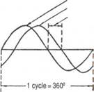
Fig. 2. Illustrating Leading Current Lagging Current Angle of Lag
Notes
analogous-аналогічний, подібний
onward -що рухається вперед
similarly-подібно
to wane -зменшувати(ся)
simultaneously-одночасно
to quote -цитувати
circuit - цикл; кругообіг
scale -розмір
to lag -відставати
to lag behind -запізнюватися
Comprehension questions:
1. How can you characterize various phases of alternating current?
2. When may two voltages or two currents not pass through the same phase at the same instant of time?
3. What can you say about phase difference measuring?
TEXT 6. INDUCTANCE
When a current flows through a conductor it sets up a magnetic field in the neighbourhood of the conductor. This is negligible in its effects in a number of cases, but there are also many cases where this magnetic field exerts a profound effect upon the circuit. The magnetic field created by the current is represented by lines of magnetic flux, these lines consisting of closed loops which are interlinked with the electric circuit, itself necessarily a closed circuit. If the current is steady, the magnetic flux is constant and produces no effect upon the circuit, but if the current changes then the strength of the magnetic field also changes. If the current increases, the total number of lines of magnetic flux is increased, so that the total number of flux-linkages is also increased. It is, however, a fundamental law that whenever the number of flux-linkages changes, an e.m.f. is induced in the circuit linked with the flux. This e.m.f. is proportional to the rate of change of linkages, and one volt is induced when the linkages change at the rate of 108 linkages per second.
Unit of Inductance.— The unit of inductance is the henry, and a circuit is said to possess an inductance of 1 henry if 1 volt is induced when the current changes at the rate of 1 ampere per second. The symbol for inductance is L, so that a circuit possesses an inductance of L henries if L volts are induced due to a rate of change of current of 1 ampere per second.
This induced e.m.f. always acts in such a direction as to oppose the change of current in the circuit, and also the magnetic flux linked with it. Thus, if the current is rising, inductance tends to oppose its growth, and if the current is falling inductance tends to oppose its decay. Examples of this effect are found in the field circuit of an ordinary generator or motor, the field circuit being highly inductive. When switched into circuit the current does not immediately rise to its full value, but grows relatively slowly, while when the switch is opened, the current tends to continue as evinced by the spark at the opening contacts.
Mutual Inductance.— When inductance is due to flux linking with the same circuit that carries the current, it is called self-inductance, in order to distinguish it from inductance due to flux linking with the circuit due to current in a neighbouring circuit, which is called mutual inductance. In the latter case, two circuits are said to possess mutual inductance if a change of current in one circuit causes an e.m.f. to be induced in the other circuit.
Two circuits are said to possess a mutual inductance of L henries if L volts are induced in one circuit due to a rate of change of current of 1 ampere per second in the other circuit. The circuit in which the current is changing is called the primary circuit, while the circuit in which the e.m.f. is induced is called the secondary circuit. When two circuits possess mutual inductance, either circuit can be employed as the primary, the value of the mutual inductance being the same, no matter which circuit is the primary and which is the secondary.
Importance of Inductance in A. C. Circuits.— Inductance is a property of a circuit, just as is resistance, and is therefore possessed by d.c. as well as a.c. circuits. In d.c. circuits, however, its effects are not apparent when the current is steady, and are only noticeable when the current is started or stopped, or when it changes in value. The reason for this is that the induced e.m.f. resulting from inductance is due to thfc rate at which the current, and therefore the flux, is changing. If the current does not change, there is no induced e.m.f. In a.c. circuits, on the other hand, the current is always changing, and therefore the e.m.f. of self-induction is always present. This modifies the value of the current and has far-reaching effects.
Notes
inductance -індуктивність
negligible -незначний
to exert -напружувати (силу)
flux -постійний рух
e.m.f.= electromotive force -електрорушійна сила
henry -одиниця самоіндукції
to evince -виявляти, показувати
circuit -цикл; кругообіг
apparent -очевидний, явний
to modify -видозмінювати
far-reaching -далекосяжний
Comprehension questions:
1. What is the unit and the symbol of inductance?
2. How do we distinguish self-inductance and inductance?
3. What properties of inductance did you learn from the text?
TEXT 7. HYSTERESIS
When a specimen of iron is carried round a magnetic cycle, a certain dissipation of energy takes place. To build up a magnetic field requires the expenditure of a certain amount of energy, and this energy is not all returned when the magnetic field is destroyed, if iron is the medium. This lost energy is dissipated in the iron in the form of heat. If the iron be now magnetized in the reverse direction, the same process is repeated, with the result that when the iron is brought back to its initial state of magnetization, an amount of energy has been expended in taking the iron round its magnetic cycle. The relation between the various values of B and H (in both positive and negative directions) is shown in Fig. 3. This effect of the dissipation of energy, due to the lagging of the flux behind the magnetizing force, is called hysteresis and the closed curve is called a hysteresis loop. It should be noted that as the value of H is raised and lowered, the curve progresses in the direction indicated by the arrows.
It can be proved that the energy dissipated in taking the iron round a magnetic cycle is proportional to the area of the hysteresis loop, so that it is desirable to employ iron having a narrow hysteresis loop. When subject to alternating magnetization, the loop is traversed once for every cycle of the current, and so the energy wasted per second is proportional to the frequency. This energy wasted per second constitutes a loss, measured in watts, and is known as the hysteresis loss. In addition to being proportional to the frequency it also depends, in a somewhat complicated manner, upon the maximum flux density attained. This is usually expressed by saying that the hysteresis loss is proportional Bx where x has a value approximately equal to 1.6 at moderate flux densities, but which may reach a value as high as 4 for extremely high flux densities.
Notes
hysteresis -гістерезис (відставання фаз)
specimen -зразок
dissipation -розсіювання; руйнування
medium -засіб, спосіб; середовище; середній
loop -петля
to constitute -складати; встановлювати
watt -ват
to attain -досягати
moderate -помірний
extremely -надзвичайно
Comprehension questions:
1. What is necessary to build up a magnetic field?
2. How do we call the lagging of the flux behind the magnetizing force?
3. How can you prove that the energy dissipated in taking the iron round a magnetic cycle is proportional to the area of the hysteresis loop?