Advantages of the shaft alternator systems
Sp 2 semester
Module 1
UNIT 1. POWER PLANTS
Shaft Alternators on Board Ships
Shaft alternators on board ships are alternators driven by the main engine to supply power to the mains. The power generation has to function properly also at changing speeds of the propulsion shaft, that is when the vessel travels at different speed ranges. This basic requirement applies to vessels with fixed pitch propellers as well as to vessels with controllable pitch propellers where, for reason of propeller efficiency optimization, both engine speed and propeller pitch are changed. Thus shaft alternator operation is also possible during manoeuvring of the vessel (operation of shaft alternator from pier to pier) with feeding of big consumers as e.g. thrusters. This results in smaller diesel generator sets.
It is a generally accepted principle to design the system in such a way that full alternator capacity is avail able at speeds between 60% and 100% of the rated speed. Apart from the relatively slow engine speed changes from one manoeuvring step to another, the system has to work properly and keep voltage and frequency constant even in case of very fast speed changes caused by heavy seas.
The use of shaft alternator systems is an especially economical solution. For this reason more and more vessels are equipped with these systems. There are many reasons to use shaft alternator systems:
Ø Lowering of fuel costs by lower heavy diesel oil cost and better efficiency of main engine
Ø Reduction of maintenance and lubricant cost by reduction of operating time of auxiliary generating sets
Ø Saving of operating personnel by simplification of ship machinery operation, as the mains is fed only by the shaft alternator system
Ø Low noise level in the engine Room
Ø Smaller diesel generator sets for operation during manoeuvring of the vessel and in harbour condition only.
Operating Principle
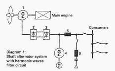
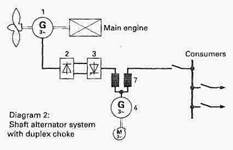
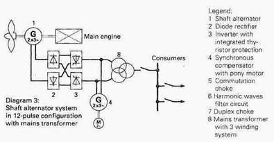
The main components of the shaft alternator systems are shown in the schematic diagrams.
The active power of variable frequency generated by the synchronous shaft alternator (1) is fed via diode rectifier (2), mains-controlled inverter (3) and commutation choke (5) respectively duplex choke (7) or mains transformer (8) to the mains. The rectifier (2) is mounted on top of the shaft alternator (1) in a space saving manner. The frequency is kept constant automatically by means of the excitation of the shaft alternator (1) by adaptation of the active power output of the inverter (3) to the respective consumer in the mains. The high speed thyristor protection system, integrated in the inverter (3), protects the inverter fuses even at extreme faults such as short circuit in the mains.
The synchronous compensator (4) controls the voltage by means of the built-in automatic voltage regulator and supplies the required reactive power for the mains and the inverter (3) as well as the short circuit current necessary for the selectivity during short circuits.
The harmonics generated by the inverter (3) have to be reduced to admissible levels according to the rules of classification societies.
Depending on the load and on the system data the shaft alternator system is configured according to the schematic diagrams with:
Ø Harmonic waves filter circuit (6),
Ø Duplex choke (7),
Ø Main transformer with 3 winding system in 12-pulse connection (8).
| 
|
|
Advantages of the shaft alternator systems
Shaft alternator systems with frequency converter supply three-phase current of constant voltage and frequency to the mains at variable main engine speed. The useful speed range of the shaft alternator can be defined on the basis of the requirements of ship operations control. For example, it is possible to select a shaft alternator speed range of 60% to 100% with constant system output and 60% to 30% with reduced system output.
Shaft alternator systems have a number of special characteristics which are of advantage both to shipping company and to shipyard:
High flexibility as regards arrangement and drive of the shaft alternator
All shaft alternator systems have one thing in common: The active power required for the mains is generated by the main engine. However the shaft alternator can be arranged and can be driven by the main engine in very diverse ways:
ü Arrangement of the shaft alternator in the shaft line between low-speed main diesel engine and propeller. This configuration with a large air gap of 7.5 mm between stator and rotor and without additional bearings has proven very successful and is the most frequent configuration used. It is particularly simple and sturdy and requires little maintenance. By contrast with certain other arrangements, torsional vibration problems relating to design and operation are not anticipated with this configuration.
ü Drive of the shaft alternator by the power takeoff of a reduction gear which is arranged between medium-speed main diesel engine and propeller. This is the usual and appropriate configuration for medium-speed main diesel engines.
ü In addition, other arrangements of the shaft alternator are also possible in principle:
· Drive directly from the crankshaft or via a reduction gear on the front end of the main diesel engine.
· Drive via a gear unit arranged in the shaft line between low-speed main diesel engine and propeller.
· Drive via a power take-off of the main diesel engine with integrated gear reducer.